- Directional Drilling
- Measurement While Drilling
- Well Planning
- End Of Well Reports
- Gamma Count Logs
- Torque & Drag Analysis
We use the most up-to-date PCPD Mud Motors to perform horizontal drilling which provides excellent speed and angle variability. Our directional services cover any type of directional well your project demands.
Directional drilling deviates from the standard vertical drilling by building well bores up from the magnetic angle of zero to ninety degrees or to any other angle between. It is the practice of drilling non-vertical wells. Many types of directional wells exist:
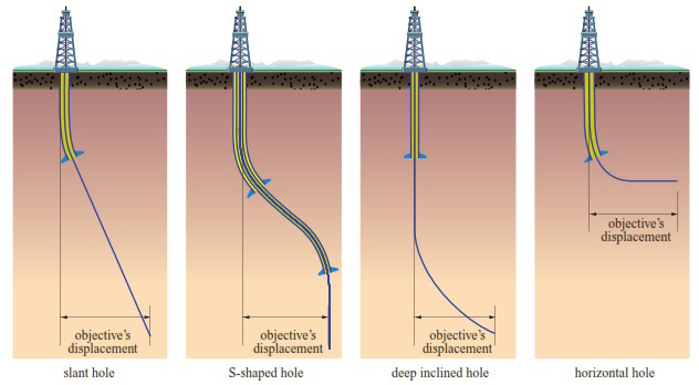
Type I – Build & Hold Trajectory (L-Profile): These wells consist of a vertical section drilled to a shallow kick-off-point, deflected angle build up to the desired angle and then the angle is held until total depth is reached.
Type II – S Profile Wells: These wells consist of a Type I well, but after the hold section, the angle is dropped to produce an S shaped well bore. This new angle is again held until total depth is reached.
Type III – Deep Kick-Off (J-Profile): Using a deeper kick-off point then Type I, the well-bore is built into the pay zone.
Type IV – Horizontal: The horizontal well starts with a vertical and is built from zero degrees to a ninety degree horizontal. The horizontal will land in the pay zone at ninety degrees and will be held in the horizontal until total depth is reached.
Horizontal drilling is used to capture oil and gas in thin pay zones. It significantly increases productivity from the lowest permeable reservoirs by exposing greater formation to the well bore. It is used to maximize the production from inefficient reservoirs.
To perform directional drilling, measurement-while-drilling tools are used to take inclination, azimuth and toolface readings of the mud motor. The MWD tools allow for accurate real-time data to be used to steer the drill bit to the intended target.
We provide the use of three different MWD tool configurations:
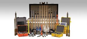
Valiant is proud to offer a new high-speed mud pulse MWD kit on par with EM speed, the first in Western Canada. Operating 3x faster then traditional mud pulse systems, at 4-5 bits/s, making it the fastest mud pulse system in the industry. The tool features new designs such as a custom mule shoe that makes the tool retrievable and re-seatable, along with integrated gamma it is hot swappable with other add-on’s such as resistivity or extra sensors. As with typical mud pulse systems, the tool has the same low operating cost and simple, fast serviceability that will help keep you up and running and at the best cost.
Our high speed mud pulse system can be utilized globally where a typical mud pulse system would be utilized.


EM Pulse tools transmit data between the tool and surface using a differential voltage between the tool and the drill string. The data is collected via ground wires on the surface which measure a signal wave and decodes the data into the required directional and gamma ray information.
We utilize the most up to date Applied Physics EM Pulse technology to complete the real-time surveying needs. This technology is a high-speed option for shallow wells in southern Alberta and Saskatchewan. Surveys are presented immediately upon making a connection resulting in the least amount of down-time while surveying.
*Images and logo courtesy of Applied Physics Systems.
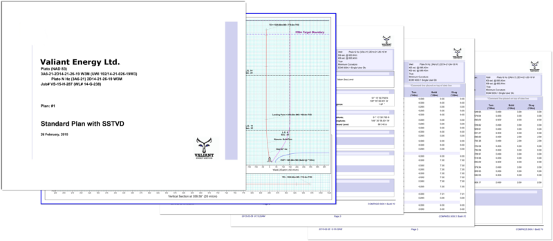
We utilize Landmark’s COMPASS well planning software for every well we design and for survey data management.
Well planning is an aspect of drilling engineering and it requires the integration of drilling engineering principles, in field experience and a keen understanding of the regions formations, faults and reservoirs. Our goal is to design the safest and lowest risk wells that can be drilled at the lowest cost to produce the highest productive output.
We provide 24 hour on call support for well plan changes and updates by our team of experienced well planners.
Anti-Collision reports are an integral part of planning in areas with existing wells. We provide anti-collision data along with well-plans that provide insight into the minimum safe distances between existing well bores, uncertainty envelopes and other undesired formations. Our reports will allow your directional drillers to maintain an appropriate and safe separation factor from undesired entities.
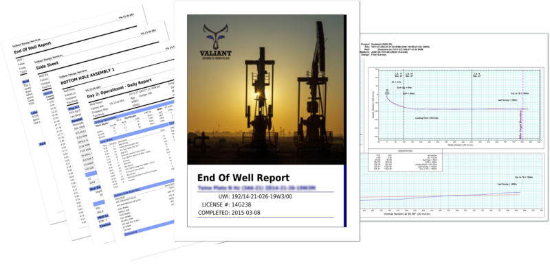
Our end of well report provides a summary of your well and includes the following information,
We utilize a detailed in-house data management and reporting system and will have the report to you the next-day upon completion of the well.
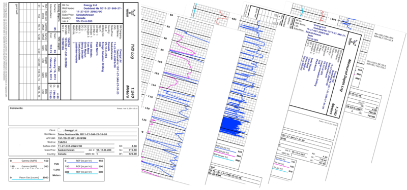
Real-time gamma ray logging is conducted alongside the MWD surveying. Gamma ray logs are used to determine the material formation that is being drilled through. By utilizing gamma counts and ROP the geologist is capable of knowing when particular formations are being encountered in real-time which eliminate the delays when relying solely on material sample analysis. This allows the drilling operation to commence at a higher speed and with greater confidence.
Gamma rays are the natural decaying isotopes within all organic materials which decay as a fixed rate. Every natural material contains radioactive isotopes which decay at different fixed rates which give each material a unique identification. Our gamma measurement equipment measures the count of gamma rays per time period which is logged in a chart according to depth. This chart provides a snapshot of what formation material exists at a particular depth, essentially providing a snapshot of the regions geological composition.
Gamma logs provide excellent insight into the regions composition and are used plan future wells with greater confidence.
Drilling highly deviated well bores raises torque and drag concerns.
Problems with drilling the lateral, running casing and well completion arise if the well bore has high torque requirements or too much drag on the string.

Torque and drag analysis is performed to validate well designs with the goal of eliminating string failure. Models of the BHA loads are calculated and analysis sub sequentially performed. The design of the well bore can be modified to ensure that torque and drag are within safe operational limits.

